
A real-time clock IC should be selected as a small power, timing and firmware subsystem, not as a generic calendar chip. Start with the processor interface and required holdover accuracy. Then verify the oscillator, backup source, alarm and memory functions, package, pinout and complete orderable code. Two RTCs can share an I2C address yet require different crystals, batteries, footprints or drivers.
What should you decide before comparing RTC part numbers?
Define six requirements before opening a product table: host interface, maximum allowable timing error, main and backup supplies, retained-memory need, environmental range and PCB constraints. This prevents a familiar part number from driving the architecture. It also exposes which fields are mandatory and which are conveniences.
Write the requirements in measurable terms. “Accurate RTC” is incomplete. State the allowed drift over the service interval and temperature range. “Battery backup” is also incomplete. Record the source chemistry, voltage window, assembly process, target holdover time and whether the RTC may communicate while the main rail is absent.
| Decision | Questions to answer | Typical consequence |
|---|---|---|
| Host interface | Does the MCU provide I2C, SPI or spare GPIO for a 3-wire port? | Changes pins, bus sharing and driver software. |
| Accuracy | What drift is allowed across the actual ambient range? | Determines whether an external crystal, MEMS RTC or TCXO is appropriate. |
| Backup power | Primary cell, rechargeable cell, supercapacitor or no backup? | Changes charging, leakage, assembly and lifetime checks. |
| Retained data | Is battery-backed SRAM required in addition to time? | May favor DS3232/DS3234-class devices over DS3231. |
| Package | Through-hole or surface mount; 8, 16 or 20 pins? | Controls footprint, assembly and possible substitution. |
| Qualification | Commercial or industrial temperature grade? | Requires the correct orderable suffix and evidence. |
The ICEARTH Real-Time Clock category provides the published product inventory. Use this guide to narrow the architecture, then use the individual product and comparison pages to verify exact orderable codes.
How do I2C, SPI and 3-wire RTC interfaces change the design?
The interface choice changes more than data rate. It determines pullups, chip-select use, address conflicts, transaction framing, startup behavior and reusable firmware. Analog Devices lists I2C, 3-wire and SPI among the available RTC interface families in its official RTC design guidance.
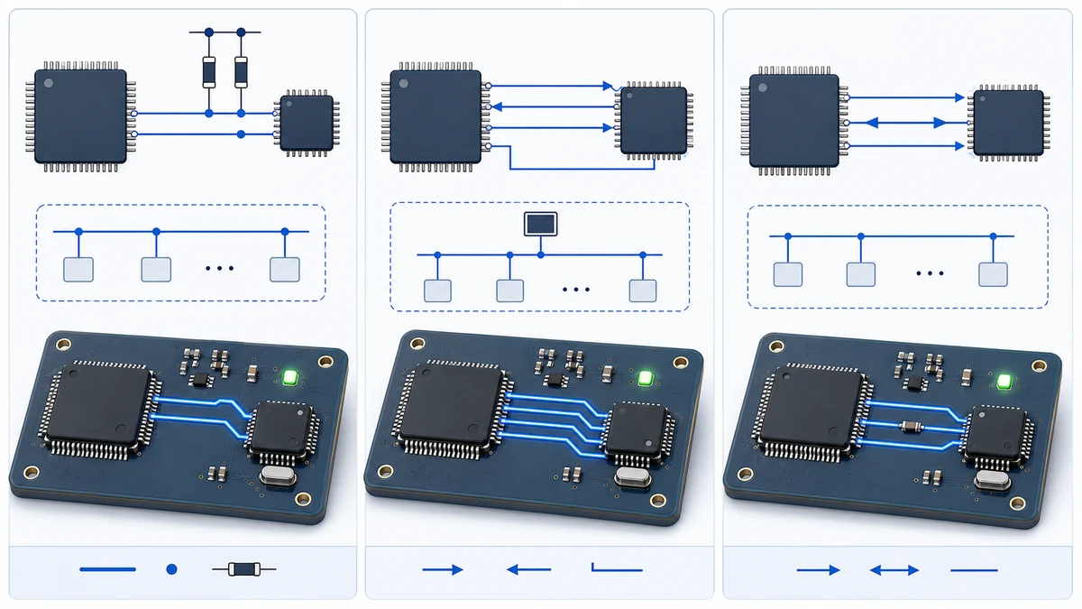
I2C RTCs
I2C is usually the natural fit when the processor already has a shared two-wire bus. DS1307 and DS1337 use I2C but do not have the same speed, supply or feature set. DS3231 and DS3232 support a fast 400 kHz I2C interface and add an integrated compensated timebase. A matching bus does not prove register or pin compatibility.
Pullup placement and power domains deserve particular attention in dual-supply designs. Analog Devices explains that accurate RTCs may remain accessible from the backup supply, so SDA and SCL must not be clamped by an unpowered rail. The same guidance recommends allowing the documented initialization period before communication after initial power application.
SPI RTCs
SPI can suit systems that already reserve a chip-select and want explicit device selection. The DS3232S# versus DS3234S# comparison shows a useful controlled example: the related devices share an integrated TCXO architecture and backed-up SRAM, while DS3232 uses I2C and DS3234 uses SPI. That interface change alters pins, driver code and bus topology.
Dedicated 3-wire RTCs
DS1302 uses a dedicated CE, I/O and SCLK scheme rather than standard I2C. It supports single-byte and burst transfers and includes a programmable trickle charger. It may fit an established legacy design, but it should not be treated as an I2C substitute merely because another RTC also uses eight pins. See the DS1302+ versus DS1307+ engineering comparison for the protocol and backup-power differences.
When does RTC accuracy justify an integrated TCXO?
An external-crystal RTC can be suitable when the system tolerates crystal, layout and temperature error. A TCXO RTC is easier to specify when drift must remain within a published ppm limit across a defined range. The decision must use the complete error budget rather than the room-temperature nominal frequency.
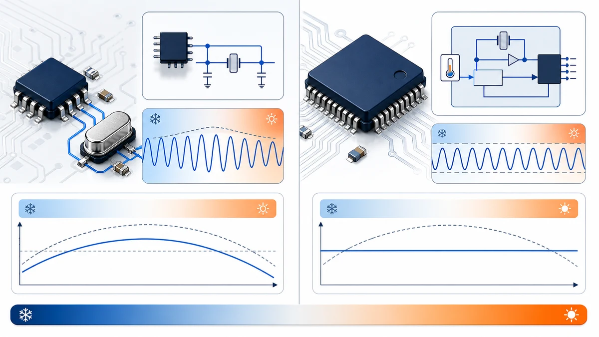
Analog Devices’ RTC design guidance notes that most RTCs use a 32.768 kHz tuning-fork crystal. Its design guidance gives a useful scale: an error of 23 ppm is roughly one minute per month. The same source warns that a crystal intended for 12.5 pF loading on an RTC designed for 6 pF will run fast. Effective capacitance, contamination, routing and temperature therefore become part of the oscillator.
DS3231 and DS3232 integrate the crystal and a temperature-compensated oscillator. Their published family specifications include +/-2 ppm from 0 deg C to +40 deg C and +/-3.5 ppm over the industrial range. DS3231M instead uses a temperature-compensated MEMS resonator and has a different accuracy specification. The DS3231M+ versus DS3231S# comparison separates oscillator technology from package and interface similarities.
Do not convert ppm to an annual drift promise without checking the applicable temperature grade, aging, supply effects and operating profile. The component limit is one input to system time accuracy. Synchronization frequency, firmware corrections and the accuracy of the reference used during test also matter.
For the deeper design decision, see Crystal RTC vs TCXO RTC: When Accuracy Justifies the Difference.
How should RTC backup power be selected?
Choose the backup source by matching voltage limits, expected holdover time, temperature, leakage, charging rules, assembly and transport constraints. Analog Devices’ backup-source guidance compares primary lithium cells, capacitors and rechargeable technologies and concludes that no single source is correct for every application.
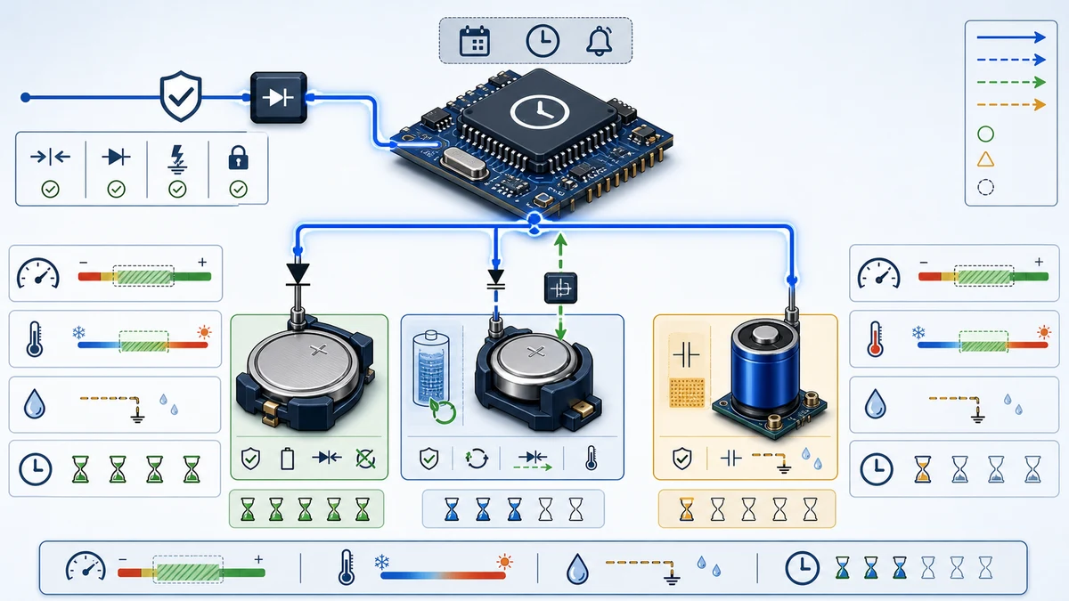
A primary cell can offer long holdover with low self-discharge, but it must never be connected to a charging output. A rechargeable cell needs a controlled charging voltage and qualified temperature range. A supercapacitor can be surface mounted and repeatedly charged, but its self-discharge and shorter backup interval may dominate the result. Calculate with worst-case RTC current, source tolerance and leakage, not a typical current alone.
Device behavior differs. DS1302 includes a programmable trickle charger and expects the designer to configure it for an appropriate rechargeable source. DS1307 uses a VBAT input and automatic switchover but does not charge the connected battery. Accurate DS323x devices also implement managed primary/backup operation, with device-specific communication and initialization behavior.
Place decoupling according to the current datasheet and application guidance. Analog Devices recommends locating the primary-supply decoupling directly at the accurate RTC. It also notes that adding a capacitor across a true backup battery can increase leakage, so a blanket “add more capacitance” rule is unsafe.
Use the detailed RTC backup power source selection and verification guide before finalizing battery chemistry, capacitor value or charger configuration.
Which RTC functions create real selection value?
Alarms, square-wave outputs, reset functions, temperature data and battery-backed memory are valuable only when they replace another system resource. Compare the exact behavior, available frequencies, pin sharing, power-domain operation and register map. Feature names alone are not sufficient.
Alarms and clock outputs
DS1337, DS3231 and DS3232 provide two time-of-day alarms, while DS1307 has no alarm registers. DS1307 does provide selectable square-wave frequencies. DS323x devices add their own interrupt and clock-output behavior. Confirm whether an output is open drain or push-pull, whether it operates from backup power and which control bits share the pin.
Battery-backed SRAM
DS1302 provides 31 bytes of backed-up RAM and DS1307 provides 56 bytes. DS3231 provides no user SRAM, while DS3232 adds 236 bytes and DS3234 provides 256 bytes. These small memories can retain calibration or application state, but firmware must define ownership, initialization and corruption handling.
The DS3231S# versus DS3232S# comparison isolates the SRAM and package decision. For industrial-temperature systems, use DS3231SN# versus DS3232SN#.
Reset and temperature information
Some accurate RTCs expose a reset function and a digital temperature reading. Treat these as defined interfaces, not generic supervisory or precision-temperature-sensor replacements. Verify thresholds, timing, accuracy and update behavior in the exact datasheet before removing another component from the design.
Why do package and order-code suffixes matter?
The full orderable code identifies package, temperature grade, lead finish and sometimes packing method. Family names do not preserve those attributes. A purchasing record that shortens DS3231SN# to DS3231 can lose the industrial-temperature requirement and make an otherwise correct quotation ambiguous.
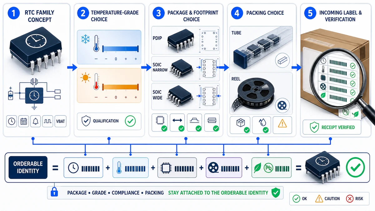
DS1302+ is an 8-pin PDIP code, while DS1302Z+ is a surface-mount SOIC option. DS1337+, DS1337S+ and DS1337U+ represent different package choices in the same family. Those package-only relationships are useful in an ordering guide, but they do not justify many nearly identical comparison pages.
Temperature suffixes can preserve more than a label. DS3231S# is the commercial-temperature code and DS3231SN# is the industrial code. The same pattern applies to DS3232S# and DS3232SN#. Their core functions align, but qualification and the applicable accuracy range must match the equipment specification.
Before releasing a BOM, compare the package drawing, body dimensions, lead pitch, pin numbering, thermal range, finish and tape-and-reel suffix. Keep the complete code on the AVL, purchase order, supplier quotation and incoming inspection record. The RTC package and ordering-code checklist provides a reusable review sequence.
What is a practical RTC selection workflow?
- Define the time requirement. Record allowed drift, synchronization interval and operating temperature.
- Select the host interface. Choose I2C, SPI, 3-wire or a legacy parallel interface based on real MCU resources.
- Choose the timebase. Decide whether an external crystal, MEMS resonator or integrated TCXO meets the accuracy and mechanical environment.
- Design backup power. Match voltage, current, leakage, holdover, charging and assembly constraints.
- Select useful functions. Specify alarms, clock outputs, reset, temperature data and retained SRAM only when needed.
- Lock the physical implementation. Verify package, pinout, footprint and oscillator layout.
- Lock the orderable code. Preserve temperature, finish and packing suffixes in every procurement document.
- Review firmware. Check register map, power-up sequence, flags, calendar handling and error recovery.
- Prototype worst cases. Test cold and hot starts, supply loss, battery switchover, bus behavior and long-duration drift.
No comparison page should replace this workflow. A comparison narrows choices; the current manufacturer datasheet and approved engineering tests control the design.
Representative RTC choices in the ICEARTH catalog
| Device | Selection role | Key caution |
|---|---|---|
| DS1302+ | 3-wire RTC with trickle charger and 31-byte RAM | Not an I2C device; charger configuration matters. |
| DS1307+ | 5 V I2C RTC with VBAT, 56-byte SRAM and SQW output | 100 kHz bus limit and external 12.5 pF crystal. |
| DS1337+ | 400 kHz I2C RTC with two alarms | No dedicated VBAT input or user SRAM. |
| DS3231S# | Integrated TCXO I2C RTC, commercial grade | No user SRAM; verify S versus SN temperature grade. |
| DS3232S# | Integrated TCXO I2C RTC with 236-byte SRAM | 20-pin footprint differs from DS3231. |
| DS3234S# | Integrated TCXO SPI RTC with 256-byte SRAM | SPI driver and pin use differ from I2C relatives. |
Frequently asked questions
These questions address the interface, accuracy, backup-power, retained-memory and qualification mistakes that most often invalidate an RTC substitution.
Is an I2C RTC interchangeable with another device at address 0x68?
No. A shared address only identifies bus selection. Supply voltage, bus speed, crystal loading, backup behavior, register map, alarms and pinout may differ. DS1307 and DS1337 demonstrate why matching an I2C address does not establish electrical, firmware or footprint compatibility.
How much drift does a ppm value represent?
Analog Devices’ RTC design guidance gives 23 ppm as approximately one minute per month. Use that only as scale. The applicable device limit, temperature profile, aging, supply effects and synchronization method determine the actual system result.
Does every VBAT pin charge the battery?
No. Many RTCs accept a backup source but do not charge it. DS1302 includes a configurable trickle charger, while DS1307 uses automatic switchover without battery charging. Verify the exact circuit before connecting a rechargeable or primary cell.
When is battery-backed SRAM useful?
Battery-backed SRAM is useful for small state that must survive main-power loss, such as calibration or event data. The examples here range from 31 bytes in DS1302 to 236 bytes in DS3232. Firmware ownership, initialization, corruption handling and backup-current impact still require review.
Can a commercial RTC grade be replaced by an industrial grade?
Functions and footprint may align within one family, but the change still requires BOM and qualification control. Verify the complete orderable code, temperature and accuracy limits, lifecycle, packing, traceability and customer approvals before substitution.
Verification method and review cadence
ICEARTH checked the four official Analog Devices resources listed below on July 27, 2026. The review compared interface guidance, oscillator and loading notes, DS323x feature differences, backup-source behavior and accurate-RTC power recommendations. It is a documentation-based selection review; it does not claim laboratory timing, battery-life or authenticity testing.
Recheck the current manufacturer data sheet, ordering table, PCN or PDN status and package drawing before design release or purchase. Review this pillar at least quarterly while its device examples remain in active selection guidance, and revise it sooner when a cited manufacturer document changes.
Editorial responsibility: This guide is published and maintained by ICEARTH. Send source discrepancies or documented corrections to [email protected] for verification against the controlling manufacturer material.
Sources and verification
- Analog Devices, Design Considerations for Analog Devices Real-Time Clocks, retrieved 2026-07-27.
- Analog Devices, Feature Comparison of the DS323x Real-Time Clocks, retrieved 2026-07-27.
- Analog Devices, Selecting a Backup Source for Real-Time Clocks, retrieved 2026-07-27.
- Analog Devices, Implementing Flawless Designs with Accurate I2C Real-Time Clocks, retrieved 2026-07-27.
This guide supports preliminary component selection and sourcing review. Confirm the latest manufacturer datasheet, ordering table and application requirements before design release or purchase.
Request an RTC component quote
Continue the engineering review
From this guide to exact component data
Related component comparisons
These comparisons contain an exact product record linked in this article.
Browse product recordsAll engineering guidesSourcing resources