
Select an RTC backup power source only after mapping the exact RTC’s power-control behavior. A pin labeled VBAT or VCC1 does not establish charging capability, switchover threshold, permissible voltage or backup current. Those facts come from the device datasheet. The source must then satisfy holdover time, temperature, assembly and service requirements without violating its chemistry.
This guide turns that review into a repeatable process for DS1302, DS1307 and DS3231 designs. For the wider component decision, begin with the real-time clock IC selection guide.
How does an RTC switch between VCC and backup power?
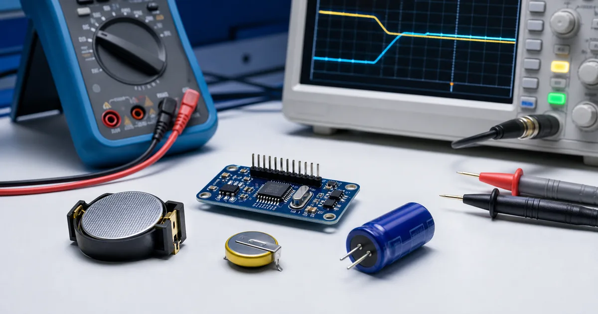
The RTC’s internal power-control circuit decides when backup takes over. Analog Devices documents that DS1307 blocks access when VCC falls below 1.25 times VBAT, then enters low-current backup after VCC falls below VBAT (DS1307 Data Sheet, 2015). Source voltage therefore affects switchover and communication.
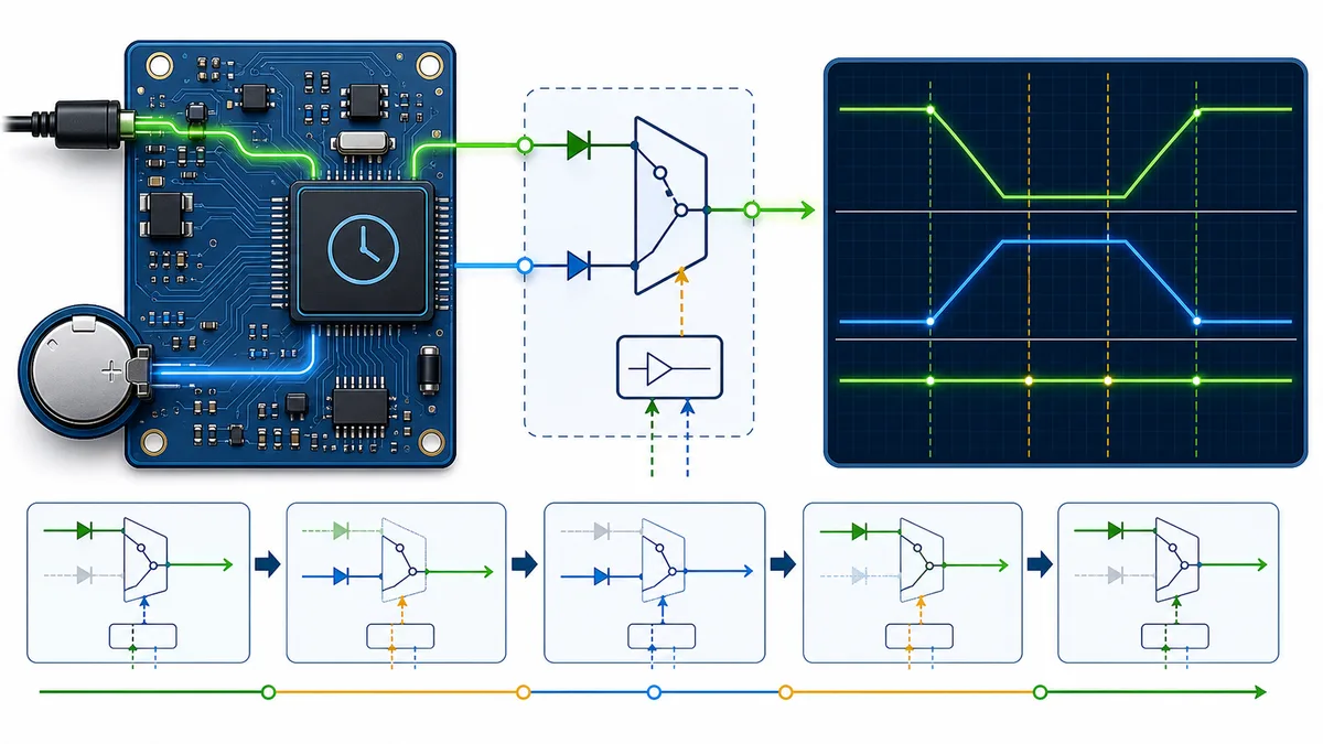
DS3231 uses a precision reference and comparator to monitor VCC and switch to its backup supply. Its interface, oscillator and outputs do not have identical availability in every supply state. Check the power-control and pin descriptions before assuming that timekeeping backup also powers host communications or external loads.
Model four conditions: normal VCC, falling VCC, backup-only operation and rising VCC. Test each transition slowly and quickly. A circuit can retain time through a clean outage yet fail when VCC lingers near a threshold or the host bus remains partly powered.
Which source type fits the required backup interval?
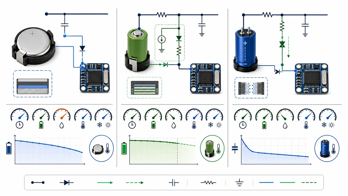
Choose chemistry from the outage profile, not habit. Analog Devices calculates that a 48 mAh BR1225 can support a DS1307 load specified at 500 nA maximum for almost 11 years in an ideal example (Selecting a Backup Source for Real-Time Clocks, 2006). Real designs must budget aging and leakage.
| Source | Best fit | Required checks |
|---|---|---|
| Primary lithium cell | Long unattended holdover | No charging path, voltage window, holder leakage, temperature, shipping and replacement |
| Rechargeable lithium cell | Repeated outages with regular main power | Qualified chemistry, charge voltage and current, cycle life and temperature |
| Supercapacitor | Shorter holdover or frequent cycling | Charger, capacitance tolerance, ESR, leakage, aging and minimum RTC voltage |
A primary cell is often the simplest long-holdover option. Confirm that no charger can feed it, then check polarity, holder resistance and contamination leakage. A rechargeable cell belongs only behind a charger approved for its chemistry. Analog Devices warns that NiMH and NiCd cells are incompatible with the float-charging method discussed for trickle-charger RTCs.
A supercapacitor suits realistic short outages and frequent cycling. Its voltage falls during discharge, so usable charge ends at the RTC’s minimum operating voltage. Analog Devices notes that capacitance can decline with use, especially at elevated temperatures. Calculate with end-of-life capacitance, maximum current and leakage.
Device-specific backup-pin behavior
The three devices require different source rules. DS1302 operates from 2.0 V to 5.5 V and draws less than 300 nA at 2.0 V, while providing a programmable trickle charger (DS1302 Data Sheet, 2015). DS1307 and DS3231 instead expose backup inputs without that DS1302 charger architecture.
DS1302: configure charging deliberately
DS1302 uses VCC2 as primary power and VCC1 as backup. Its trickle-charge register selects enable state, diode count and a documented resistor path. The charger powers up disabled. Preserve that default until the assembled source is identified and the configuration passes a worst-case charge calculation.
Calculate maximum initial current from the highest VCC2, selected diode condition, resistor tolerance and lowest source voltage. Compare the result with the source manufacturer’s limits. For a primary cell, leave charging disabled and verify firmware cannot enable it accidentally.
DS1307: treat VBAT as an input
DS1307 specifies VBAT for a standard 3 V lithium cell or another compliant source. Its datasheet says a series diode may prevent proper operation, so don’t add one without checking voltage loss. If backup isn’t required, ground VBAT as directed instead of leaving it floating.
DS3231: verify backup operating modes
DS3231 automatically switches to VBAT when VCC is unsuitable. Backup current depends on conditions defined in its electrical tables. Use the maximum applicable value, not a headline typical value. See the DS3231S# product page, then confirm the current Analog Devices datasheet.
The DS1302+ versus DS1307+ comparison isolates the charging and interface differences. The DS1302+ and DS1307+ pages help preserve the exact orderable device during sourcing.
How should backup current, voltage and holdover be calculated?
Start with maximum backup current for the actual mode. Analog Devices specifies 500 nA maximum for DS1307 timekeeping with SQW/OUT off (Design Considerations for Analog Devices Real-Time Clocks, 2011). Add source self-discharge and every parallel leakage path before converting capacity into time.
For a cell, divide usable ampere-hours by total worst-case amperes for a first estimate. Derate capacity for temperature, aging, discharge limits and service margin. Don’t call the quotient guaranteed life. Holder resistance and board contamination may impose separate limits even when average current looks acceptable.
For a supercapacitor, estimate time from capacitance multiplied by allowed voltage drop, divided by total discharge current. The drop runs from qualified charge voltage to the RTC’s minimum backup voltage. Analog Devices recommends maximum backup current plus capacitor leakage, tolerance and voltage-dependent discharge behavior.
Separate energy qualification from threshold qualification. A source can store ample energy yet cross a switchover or access threshold at the wrong moment. Plot VCC, VBAT and bus lines during ramp tests, then correlate traces with register reads and elapsed-time continuity.
Qualification tests before release
Qualification must cover limits and transitions, not one room-temperature outage. The DS1307 datasheet states that a 48 mAh lithium battery can provide more than 10 years of backup at +25°C under stated conditions (DS1307 Data Sheet, 2015). That statement doesn’t replace testing your source, PCB and environment.
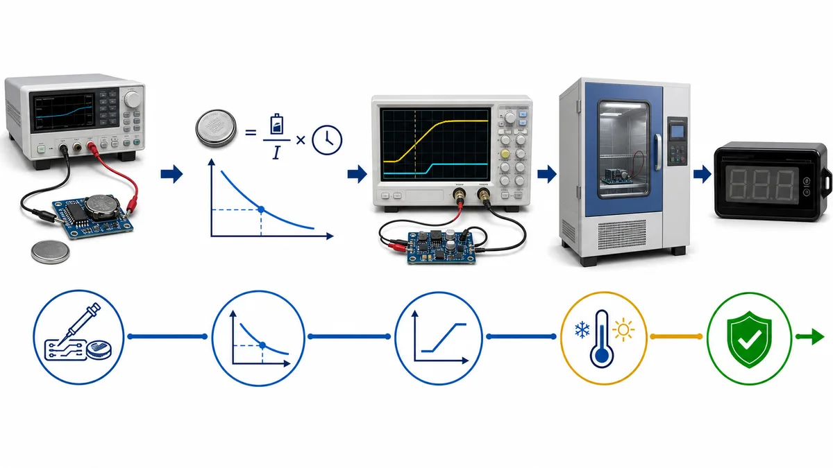
- Confirm the exact part. Record suffix, datasheet revision, backup limits and applicable current row.
- Audit the schematic. Identify every source path, including pullups, protection parts and test equipment.
- Measure current. Test fresh, nominal and near-end source voltages across qualified temperatures.
- Exercise ramps. Apply fast drops, slow brownouts, interrupted ramps and repeated cycles.
- Test recovery. Confirm time, oscillator, flags, alarms and communications after VCC returns.
- Validate charging. Measure maximum current, terminal voltage, recharge time and temperature where charging is allowed.
- Age margins. Repeat critical checks with worst-case capacitance, leakage and cell condition.
- Protect firmware. Verify charger configuration and detect invalid time at startup.
Which failure modes most often escape review?
Threshold, leakage and charging errors cause deceptive failures. DS1307 may deny access when VCC falls below 1.25 times VBAT before it switches fully to backup (Selecting a Backup Source for Real-Time Clocks, 2006). A bench test at one fixed voltage can miss that transition.
- Primary cell is charged: a charger bit, pullup or fixture sends current into it.
- Supercapacitor never fills: charge resistance, duty cycle or leakage prevents recovery.
- Current is measured incorrectly: meter burden voltage changes VBAT or operating mode.
- Communication is expected on backup: firmware assumes the bus remains available.
- Time resets after assembly: the source is absent, reversed, discharged or isolated by voltage drop.
- Capacity hides end-of-life behavior: temperature, aging and self-discharge consume the margin.
Keep the source calculation, charger state and threshold tests in the design record. Changes to chemistry, holder or capacitor series require review, even when nominal voltage and capacity stay unchanged.
Frequently asked questions
These answers address the charging, leakage, voltage-threshold and no-backup conditions that most often invalidate an RTC backup-source design.
Can I connect a CR coin cell to DS1302?
Yes, if its voltage meets DS1302 limits and charging remains disabled. Calculate life with the applicable maximum backup current, cell self-discharge and every board leakage path. Keep the charger disabled for a primary cell and add a firmware safeguard against accidental activation.
Can DS1307 recharge its backup battery?
No. DS1307 provides a VBAT input and automatic switchover, not the DS1302 charger. Its backup current is specified at 500 nA maximum with SQW/OUT off. Use a primary 3 V lithium cell or another compliant source without assuming that the RTC will charge it.
Is a supercapacitor always better for frequent outages?
No. Its voltage declines during backup. Estimate holdover from capacitance multiplied by the usable voltage change and divided by maximum RTC current plus leakage. A supercapacitor fits only when worst-case capacitance, leakage, recharge time and the real outage profile all meet the design target.
Why can a higher VBAT create a problem?
DS1307 inhibits access below approximately 1.25 times VBAT, so increasing VBAT also raises that access threshold and can reduce VCC headroom during a brownout. Stay within the specified range and test both falling and rising supply ramps instead of maximizing the backup voltage.
Should VBAT be left open when no backup is fitted?
Not on DS1307. Its data sheet directs designers to ground VBAT when backup is not required. This instruction is device-specific, so check the exact RTC rather than applying it universally. Unintended backup loss can affect retained application data as well as time.
Verification method and review cadence
ICEARTH checked the six official Analog Devices resources listed below on July 27, 2026. The review compared the device data sheets with the manufacturer’s backup-source, supercapacitor and RTC design notes for voltage limits, supply thresholds, maximum backup current, charging behavior and holdover calculations.
This is a documentation-based engineering review. It does not claim laboratory battery-life testing, assembled-board leakage testing or component-authenticity verification. Before release, repeat the calculation with the selected source data and test the complete PCB over its qualified supply and temperature limits.
Review this guide at least quarterly while its examples remain in active design guidance, and update it sooner after a cited data-sheet revision, PCN, PDN or source-chemistry change. Send documented discrepancies to [email protected] for checking against the controlling manufacturer material.
Which official sources support these checks?
Six official Analog Devices documents support this process: three device datasheets and three design notes. The backup-source note includes the 48 mAh, 500 nA example (Analog Devices, 2006). Confirm the latest revision before design release.
- Analog Devices, DS1302 Data Sheet, Rev. 4, retrieved 2026-07-27.
- Analog Devices, DS1307 Data Sheet, Rev. 5, retrieved 2026-07-27.
- Analog Devices, DS3231 Data Sheet, Rev. 10, retrieved 2026-07-27.
- Analog Devices, Selecting a Backup Source for Real-Time Clocks, retrieved 2026-07-27.
- Analog Devices, Estimating Super Capacitor Backup Time on Trickle-Charger Real-Time Clocks, retrieved 2026-07-27.
- Analog Devices, Design Considerations for Analog Devices Real-Time Clocks, retrieved 2026-07-27.
Continue the engineering review
From this guide to exact component data
Related component comparisons
These comparisons contain an exact product record linked in this article.
Browse product recordsAll engineering guidesSourcing resources